
47 Precision Time Protocol #
47.1 Introduction #
Precision Time Protocol (PTP), defined by the IEEE 1588 standard, distributes
highly accurate time across a packet network. When the network interface cards
(NICs) timestamp PTP packets in hardware, it reaches sub-microsecond accuracy,
well beyond what NTP can offer. In telco environments PTP is a core building
block of 5G radio access networks (RAN), where the radio units require tight
phase and time alignment to transmit correctly. SUSE Telco Cloud implements PTP
through the linuxptp package and targets the telco profiles ITU-T G.8275.1 and
ITU-T G.8275.2 described below.
A PTP domain is built from a small set of clock roles:
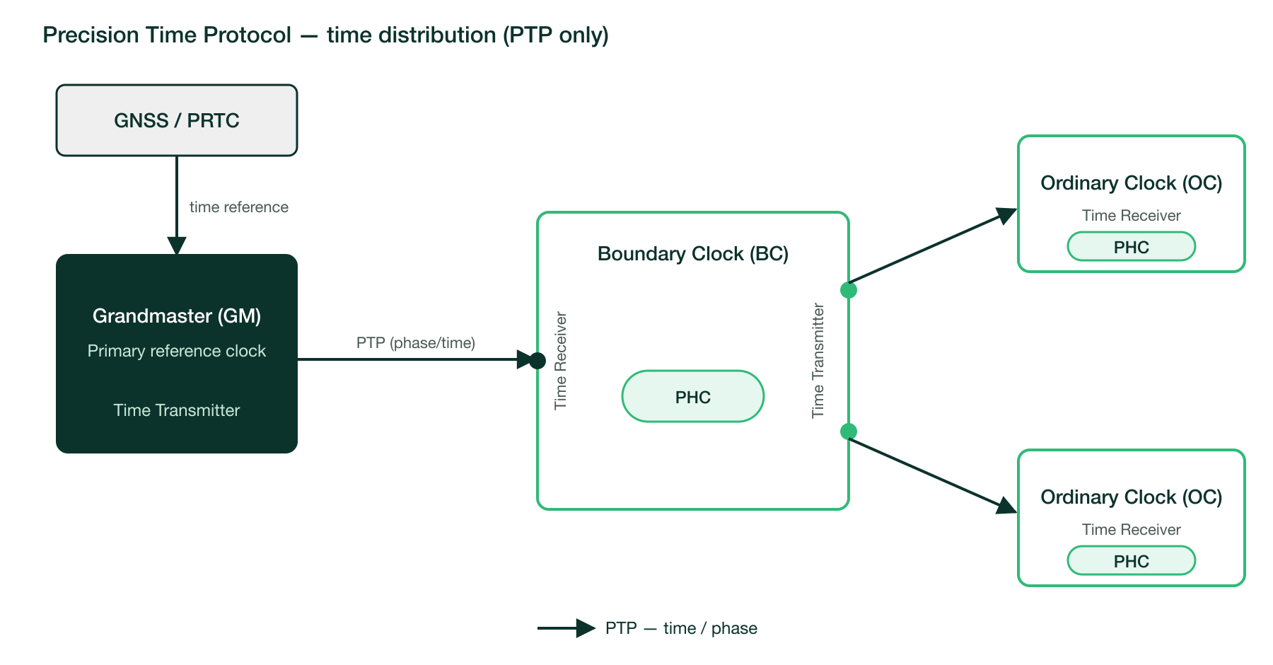
Grandmaster (GM): the primary source of time for the domain. It is normally locked to a Primary Reference Time Clock (PRTC), usually driven by a GNSS receiver, and transmits time towards the downstream nodes. The accuracy of the GM sets the quality ceiling for the whole domain.
Ordinary Clock (OC): an end node with a single PTP port. In a telco deployment it acts as a Time Receiver, disciplining its local clock from an upstream Grand Master or Boundary Clock. A compute node running a radio workload is a typical OC.
Boundary Clock (BC): a multi-port node that receives time on one port (Time Receiver) and regenerates it towards other nodes on its remaining ports (Time Transmitter). Inserting Boundary Clocks along the path shortens the chain between each OC and the reference, limiting the error the network would otherwise accumulate hop after hop.
The distinction between an Ordinary Clock and a Boundary Clock is central when designing the topology:
An Ordinary Clock has a single PTP port and sits at the edge of the domain. It only consumes time to discipline its own clock and never forwards time to other nodes.
A Boundary Clock has multiple PTP ports. It consumes time on its Time Receiver port and regenerates it on its Time Transmitter ports, terminating the upstream timing chain and starting a new one downstream. This regeneration is what prevents error from accumulating across a long chain of nodes.
The following hardware and signalling elements support these roles:
PTP Hardware Clock (PHC): the clock built into the NIC that PTP actually synchronizes. Aligning the operating system clock to the PHC is a separate step handled by a dedicated daemon.
Synchronous Ethernet (SyncE): physical-layer frequency synchronization. PTP carries phase and time inside packets, whereas SyncE recovers a stable frequency directly from the Ethernet signal. SyncE is an optional enhancement: PTP on its own already delivers phase and time, and SyncE is added only when a node needs stronger frequency stability and longer holdover should the PTP time source be temporarily lost.
Digital Phase-Locked Loop (DPLL): a hardware timing block that locks onto a reference signal and filters it to output a stable, clean clock. It is what disciplines the PHC from the available inputs and, on platforms with more than one NIC, keeps the different NIC clocks aligned.
On each node these functions are carried out by the linuxptp daemons: ptp4l
runs the PTP protocol and disciplines the PHC, and phc2sys aligns the system
clock to the PHC. On a Grandmaster, ts2phc additionally steers the PHC from the
GNSS reference. Their roles and installation are covered in Section 47.2, “Prerequisites”.
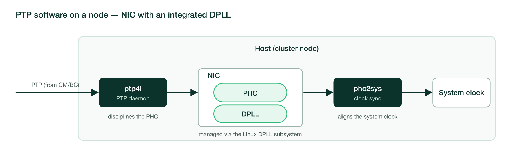
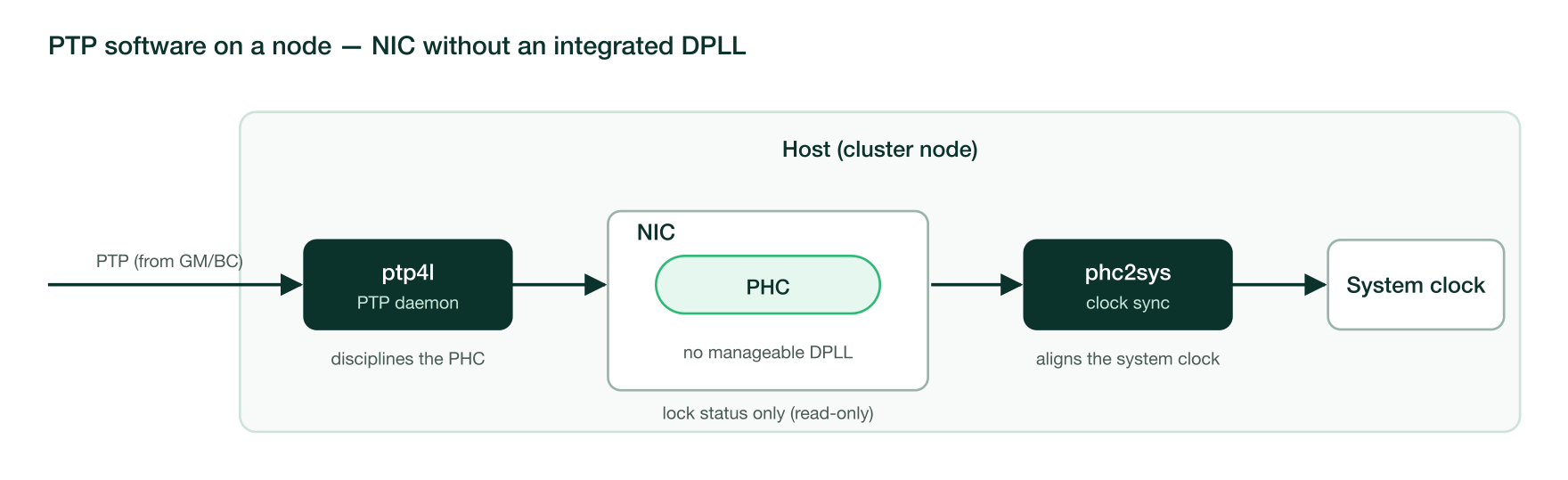
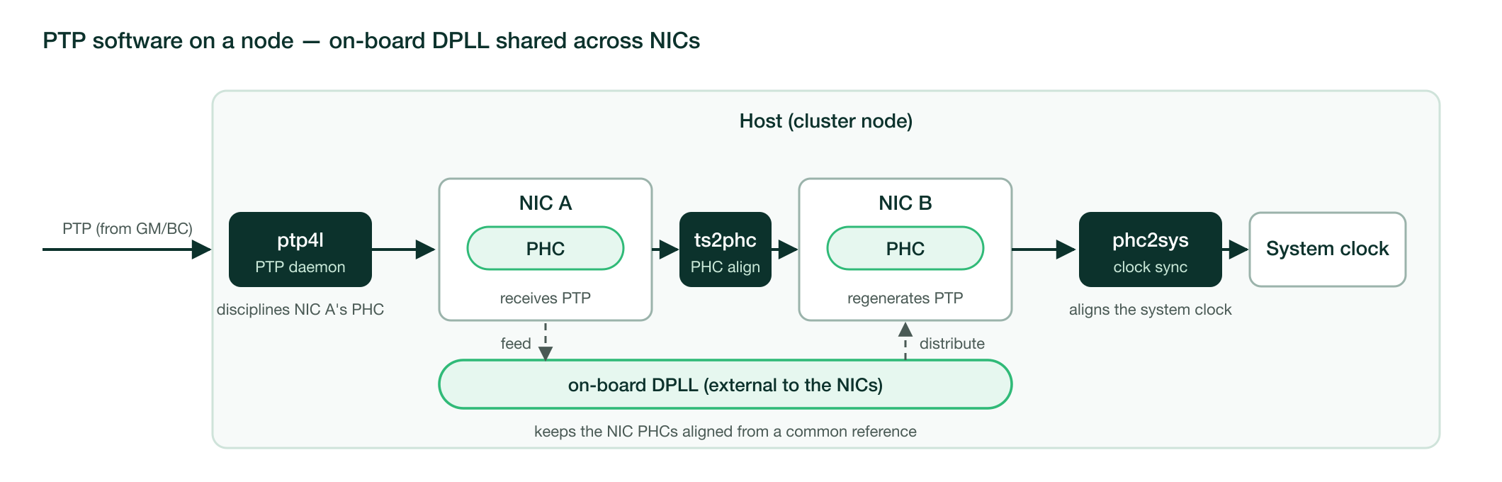
The hardware clock itself is handled by the Linux kernel DPLL subsystem together with the network driver. The degree of timing control, and how timing is distributed within a multi-NIC node, depends on where the manageable DPLL sits:
NIC with an integrated DPLL: the DPLL is embedded in the NIC and is configured through the Linux DPLL subsystem. It selects and locks to the chosen reference and disciplines the PHC, giving full control over frequency and holdover.
NIC without an integrated DPLL: the NIC exposes no configurable DPLL.
ptp4ldisciplines the PHC directly, and the subsystem can at most report the lock status (read-only); advanced frequency handling then relies on an external timing source.On-board DPLL shared across several NICs: the DPLL is not embedded in a single NIC but sits on the platform, external to the NICs. It disciplines and keeps the PHCs of several NICs aligned from a common reference, so every NIC in the node shares the same time. This arrangement is used on multi-NIC platforms that distribute timing internally instead of relying on external cabling.
Telco networks standardize on two ITU-T profiles, which differ mainly in the transport used and in how much of the underlying network must be PTP-aware:
ITU-T G.8275.1 (full timing support): runs directly over Ethernet (Layer 2) using multicast. Every node along the path must be PTP-aware and act as a Boundary Clock, which yields the highest accuracy. Unless stated otherwise, the scenarios in this guide use this profile.
ITU-T G.8275.2 (partial timing support): runs over IP (Layer 3) using unicast. Intermediate nodes are not required to support PTP, so timing can cross network segments that are not timing-aware, at the cost of lower accuracy.
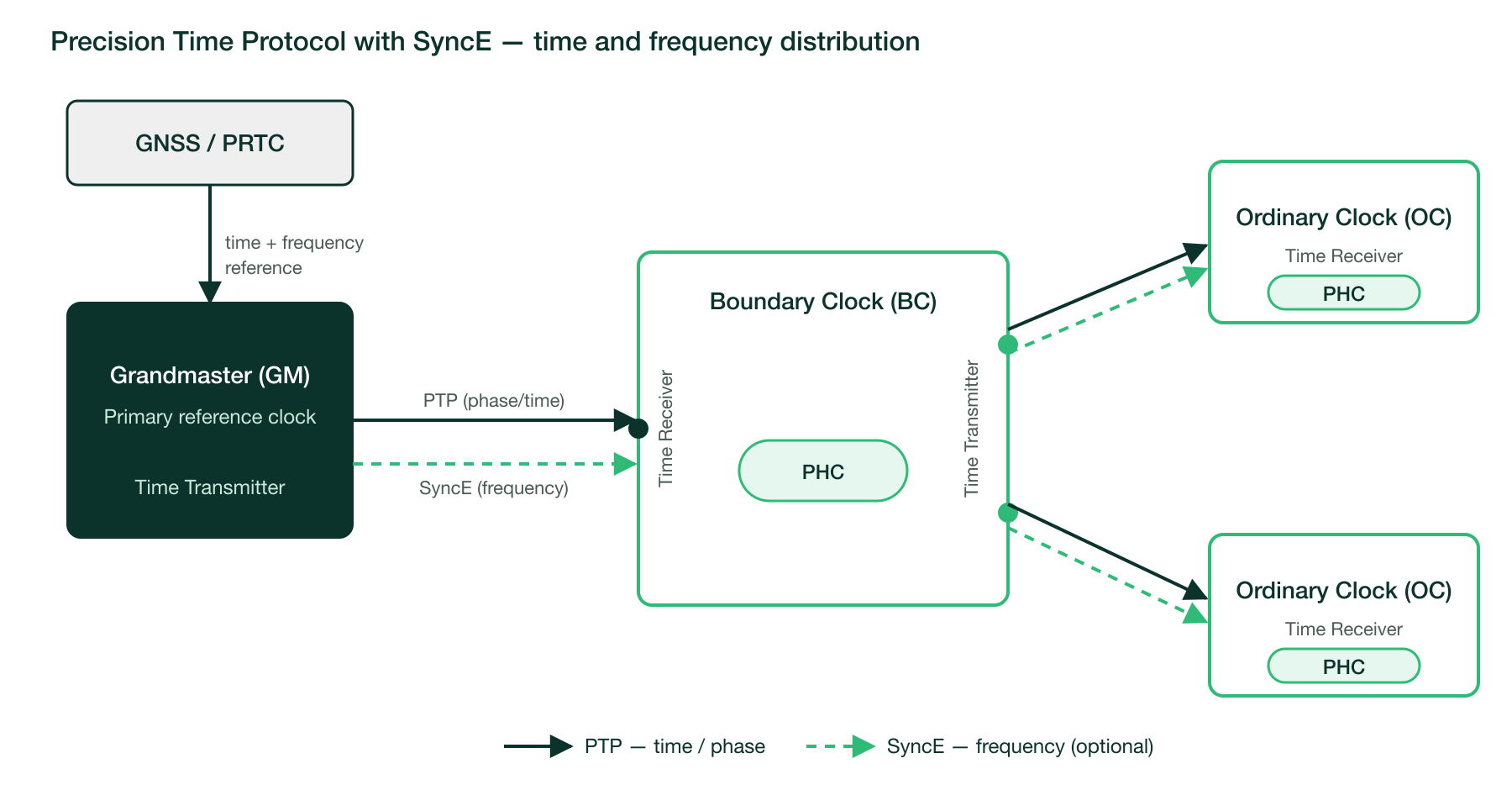
The following figures show time distribution with PTP only and with SyncE added as an optional frequency enhancement. In both cases the Grandmaster derives its reference from a PRTC/GNSS source and the Boundary Clock regenerates timing towards the endpoints.
The following scenarios are covered in this guide. Each scenario includes a link to its Cluster API (CAPI) automation.
Scenario 1a - Ordinary Clock (PTP-only) (Section 47.3, “Scenario 1a - Ordinary Clock (PTP-only)”)
Scenario 1b - Ordinary Clock (Hybrid mode: PTP & SyncE) (Section 47.4, “Scenario 1b - Ordinary Clock (Hybrid mode: PTP & SyncE)”)
Scenario 2a - Boundary Clock (PTP-only) with Multiport Single NIC including propagation to Ordinary Clock server (Section 47.5, “Scenario 2a - Boundary Clock (PTP-only) with Multiport Single NIC including propagation to Ordinary Clock server”)
Scenario 2b - Boundary Clock (Hybrid mode: PTP & SyncE) with Multiport Single NIC including propagation to Ordinary Clock server (Section 47.6, “Scenario 2b - Boundary Clock (Hybrid mode: PTP & SyncE) with Multiport Single NIC including propagation to Ordinary Clock server”)
Scenario 3a - Boundary Clock (PTP-only) Multi-NIC with internal timing module (DPLL GNR-D based) (Section 47.7, “Scenario 3a - Boundary Clock (PTP-only) Multi-NIC with internal timing module (DPLL GNR-D based)”)
Scenario 3b - Boundary Clock (Hybrid mode: PTP & SyncE) Multi-NIC with internal timing module (DPLL GNR-D based) (Section 47.8, “Scenario 3b - Boundary Clock (Hybrid mode: PTP & SyncE) Multi-NIC with internal timing module (DPLL GNR-D based)”)

Only Scenario 1a (Section 47.3, “Scenario 1a - Ordinary Clock (PTP-only)”) shows the configuration for both telco profiles,
ITU-T G.8275.1 and ITU-T G.8275.2. The remaining scenarios focus only on the ITU-T G.8275.1
case for brevity: the deployment is identical and only the ptp4l configuration file
changes between the two profiles.
47.2 Prerequisites #
This guide covers only telco-specific profiles, so hardware time-stamping and a PTP
hardware clock (PHC) in the NIC are assumed. Telco-grade network adapters provide
PTP support in hardware; you can confirm the capabilities of a given interface with
ethtool -T:
# ethtool -T eno16495np0
Time stamping parameters for eno16495np0:
Capabilities:
        hardware-transmit
        software-transmit
        hardware-receive
        software-receive
        software-system-clock
        hardware-raw-clock
PTP Hardware Clock: 0
Hardware Transmit Timestamp Modes:
        off
        on
Hardware Receive Filter Modes:
        none
        all
Check for the hardware-transmit, hardware-receive and hardware-raw-clock
capabilities and a PTP Hardware Clock index of 0 or higher (a value of -1 means
the interface has no PHC). Replace eno16495np0 with the interface you intend to use for
PTP.
PTP is provided by the linuxptp package. It ships three user-space programs —
ptp4l, phc2sys and ts2phc — that run as long-running daemons managed by
systemd (a dedicated service each: ptp4l.service, phc2sys.service, and
ts2phc.service). Collectively, they execute the protocol and keep the clocks
synchronized:
ptp4l: the PTP daemon. It runs the IEEE 1588 protocol on the configured interfaces, applies the Best Master Clock Algorithm (BMCA) to determine the role of each port, and disciplines the NIC’s PHC. A singleptp4linstance can manage several ports, which is what allows a node to act as a Boundary Clock.phc2sys: synchronizes two clocks. It is typically used to align the system (operating system) clock to the PHC thatptp4lkeeps synchronized, so that the system time also follows PTP.ts2phc: "time stamp to PHC". It disciplines the PHC from an external time signal, such as the PPS delivered by a GNSS receiver. It is used on a Grandmaster and to keep multiple PHCs aligned within the same node.
The recommended way to install PTP on a downstream cluster is to add the
linuxptp package to the packageList of the Edge Image Builder (EIB) definition
file, so that it is deployed automatically during provisioning. See the
EIB documentation (Section 5.3.6, “Configuring RPM packages”) for
more information on installing packages.
apiVersion: 1.3
image:
  imageType: RAW
  arch: x86_64
  baseImage: SL-Micro.x86_64-6.2-Base-RT-GM.raw
  outputImageName: eibimage-slmicrort-telco.raw
operatingSystem:
  systemd:
    enable:
      - ptp4l
      - phc2sys
  packages:
    packageList:
      - linuxptp
sccRegistrationCode: $SCC_REGISTRATION_CODEThe linuxptp package does not enable ptp4l, phc2sys, or ts2phc by default.
After deploying the configuration files, use the systemd section of the manifest
to enable the required node daemons (see the scenarios below).
Finally, the PTP profile in use determines whether the network switches between nodes must be configured as PTP-aware devices:
ITU-T G.8275.1 (full timing support): runs directly over Ethernet (Layer 2) using multicast. Every node along the path must be PTP-aware and act as a Boundary Clock, which yields the highest accuracy; the intervening switches must therefore be configured for PTP. Unless stated otherwise, the scenarios in this guide use this profile.
ITU-T G.8275.2 (partial timing support): runs over IP (Layer 3) using unicast. Intermediate nodes are not required to support PTP, so timing can cross network segments that are not timing-aware and the switches do not need PTP configuration, at the cost of lower accuracy.
47.3 Scenario 1a - Ordinary Clock (PTP-only) #
Explanation
This is the simplest PTP deployment: a single cluster node consumes time from an upstream source and disciplines its local clocks, without ever forwarding time to another node. The node runs as an Ordinary Clock (OC) with a single PTP port in the Time Receiver role.
On the OC node the timing is handled entirely by the linuxptp daemons, regardless
of the profile in use. No DPLL configuration or ts2phc is required, because the
node uses a single NIC and ptp4l disciplines its PHC directly:
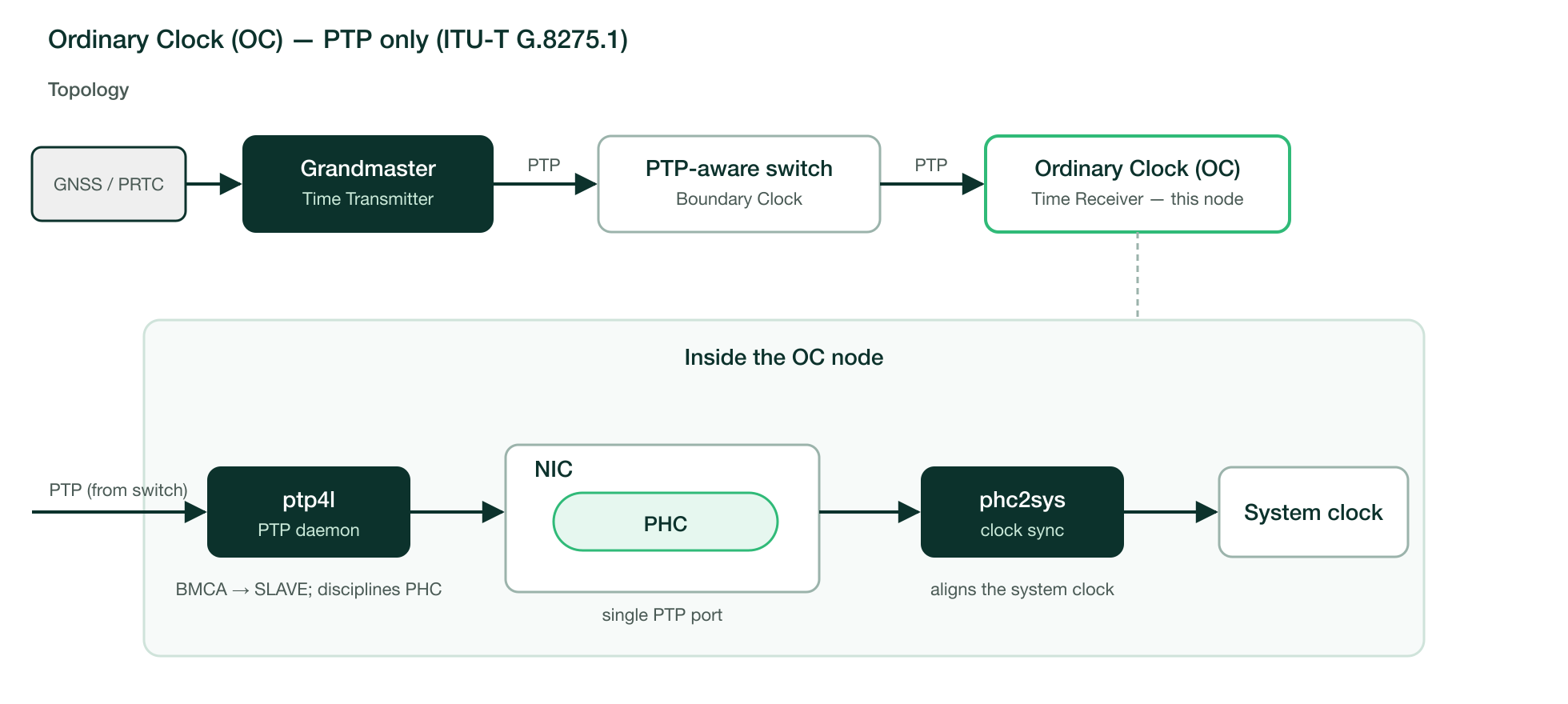
ptp4lruns the PTP protocol on the receiving interface. The Best Master Clock Algorithm (BMCA) selects the upstream node as the master, the local port transitions to theSLAVEstate andptp4ldisciplines the NIC’s PTP Hardware Clock (PHC). SettingclientOnly 1restricts the node to the Time Receiver role, so it can never be selected as a master.phc2sysaligns the system clock (CLOCK_REALTIME) to the PHC thatptp4lkeeps synchronized, so the operating-system time also follows PTP.
The scenario can be implemented with either telco profile. They differ in transport and in what the intervening network must provide, and are documented below as two independent models:
Model 1 — ITU-T G.8275.1 (Section 47.3, “Scenario 1a - Ordinary Clock (PTP-only)”) (Layer 2 multicast): use it when every hop between the master and the OC is PTP-aware. It provides the highest accuracy and is the default for telco deployments.
Model 2 — ITU-T G.8275.2 (Section 47.3, “Scenario 1a - Ordinary Clock (PTP-only)”) (Layer 3 unicast): use it when the OC must reach the master across a network that is not PTP-aware, at the cost of lower accuracy.

An Ordinary Clock runs a single PTP profile at a time. The two models are mutually
exclusive: configure only one of them on a given node. Create only the configuration
file of the chosen profile and reference only that file in /etc/sysconfig/ptp4l. Do
not create both /etc/ptp4l-G.8275.1.conf and /etc/ptp4l-G.8275.2.conf, and never
pass both files to the OPTIONS= line.
Model 1 — ITU-T G.8275.1 (Layer 2 multicast)
G.8275.1 runs directly over Ethernet and addresses its messages to the
non-forwardable multicast MAC 01:80:C2:00:00:0E, which standard bridges do not
forward, so every device on the path must terminate and regenerate PTP. The
components are:
Grandmaster (GM): the upstream reference for the PTP domain (domain
24for G.8275.1), typically locked to a GNSS/PRTC source.PTP-aware switch: acts as a Boundary Clock. Its port towards the GM is a Time Receiver and its port towards the OC is a Time Transmitter. Both ports must have PTP enabled.
Ordinary Clock (OC): the cluster node, receiving time on its single PTP port.
Configure the node as follows:
Identify the PHC index
<N>of the interface used for PTP (hereeno8403np1); the value of the printed fieldPTP Hardware Clock(which may also appear asHardware timestamp provider index) gives the/dev/ptp<N>device thatptp4ldisciplines and thatphc2sysreads as its source:# ethtool -T eno8403np1 Time stamping parameters for eno8403np1: Capabilities: hardware-transmit hardware-receive hardware-raw-clock PTP Hardware Clock: 1 ...In this example the PHC of
eno8403np1is/dev/ptp1.Create the
ptp4lconfiguration file/etc/ptp4l-G.8275.1.conf. The interface is declared as a section ([eno8403np1]), so the daemon does not need the-iflag:Example 47.1: Ordinary Clock configuration — ITU-T G.8275.1 ## Telecom G.8275.1 — Ordinary Clock (Time Receiver) [global] domainNumber 24 priority2 255 dataset_comparison G.8275.x G.8275.portDS.localPriority 128 G.8275.defaultDS.localPriority 128 maxStepsRemoved 255 logAnnounceInterval -3 logSyncInterval -4 logMinDelayReqInterval -4 announceReceiptTimeout 3 clientOnly 1 ptp_dst_mac 01:80:C2:00:00:0E network_transport L2 summary_interval 3 message_tag "ptp4l" uds_address /var/run/ptp4l uds_ro_address /var/run/ptp4lro [eno8403np1]
The
ptp_dst_macvalue is fixed for G.8275.1: it is the non-forwardable multicast address01:80:C2:00:00:0Ethat confines PTP to a single link and is the reason why every device on the path must be PTP-aware. Theuds_addressexposes a management socket thatphc2sysuses to follow the port state.Point
ptp4lat this file in/etc/sysconfig/ptp4l:OPTIONS="-f /etc/ptp4l-G.8275.1.conf"
Configure
phc2sysin/etc/sysconfig/phc2systo discipline the system clock from the PHC of the PTP interface (/dev/ptp1). The--uds_addressand--domainNumbervalues must match theptp4lconfiguration:OPTIONS="-s /dev/ptp1 -w -m --uds_address /var/run/ptp4l --domainNumber 24"
-s /dev/ptp1selects the PHC as the source clock,-wwaits forptp4lto synchronize before stepping the system clock, and-mprints the servo status to the log.Enable and start both services:
# systemctl enable --now ptp4l phc2sysVerify that
ptp4lhas locked to the upstream master. The port moves toSLAVEand the reported offset (rms) converges to a low, stable value:# journalctl -u ptp4l -f ptp4l[...]: "ptp4l" port 1 (eno8403np1): UNCALIBRATED to SLAVE on MASTER_CLOCK_SELECTED ptp4l[...]: "ptp4l" rms 1502498567 max 8499416372 freq -3977 +/- 43609 delay 11 +/- 607 ptp4l[...]: "ptp4l" rms 40 max 99 freq +10129 +/- 30 delay 211 +/- 3 ptp4l[...]: "ptp4l" rms 7 max 15 freq +10125 +/- 13 delay 211 +/- 2 ptp4l[...]: "ptp4l" rms 6 max 16 freq +10118 +/- 12 delay 213 +/- 2Verify that
phc2sysis disciplining the system clock. The servo state progresses froms0(unlocked) throughs1(initial step) tos2(locked), and the offset settles around zero:# journalctl -u phc2sys -f phc2sys[...]: CLOCK_REALTIME phc offset 45583145631 s0 freq -1673 delay 0 phc2sys[...]: CLOCK_REALTIME phc offset 45583157513 s1 freq +10207 delay 0 phc2sys[...]: CLOCK_REALTIME phc offset 4 s2 freq +10211 delay 0 phc2sys[...]: CLOCK_REALTIME phc offset 13 s2 freq +10221 delay 0A steady
s2state with a small offset confirms that the node is locked and the system clock is following PTP.
Model 2 — ITU-T G.8275.2 (Layer 3 unicast)
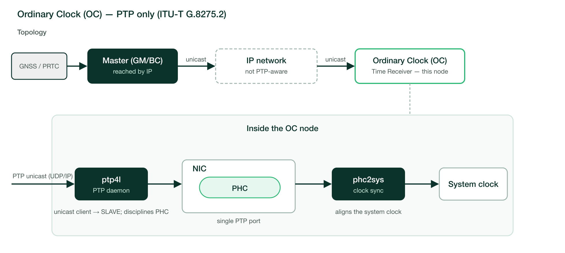
G.8275.2 runs over IP (Layer 3) using unicast: the OC exchanges messages directly with the master’s IP address, so the intervening network does not need to be PTP-aware and no PTP-enabled switch is required. The components are:
Master (GM or Boundary Clock): the upstream master, reachable by IP on the G.8275.2 domain (domain
44).IP network: a standard routed or switched network. It forwards the unicast PTP packets without any PTP configuration.
Ordinary Clock (OC): the cluster node, sending unicast requests to the master from its single PTP port.
Configure the node as follows:
Identify the PHC of the PTP interface as in Model 1 (
ethtool -T eno8403np1); in this example the PHC ofeno8403np1is/dev/ptp1.Create the
ptp4lconfiguration file/etc/ptp4l-G.8275.2.conf. There is noptp_dst_mac, because the master is reached by IP through theunicast_master_table. Replace$MASTER_IP_ADDRESSwith the IP address of the upstream master:Example 47.2: Ordinary Clock configuration — ITU-T G.8275.2 ## Telecom G.8275.2 — Ordinary Clock (Time Receiver) [global] domainNumber 44 priority2 255 dataset_comparison G.8275.x G.8275.portDS.localPriority 128 G.8275.defaultDS.localPriority 128 maxStepsRemoved 255 logAnnounceInterval 0 logSyncInterval -5 logMinDelayReqInterval -4 announceReceiptTimeout 2 clientOnly 1 network_transport UDPv4 hybrid_e2e 1 inhibit_multicast_service 1 unicast_listen 1 unicast_req_duration 60 message_tag "ptp4l" uds_address /var/run/ptp4l uds_ro_address /var/run/ptp4lro [unicast_master_table] table_id 1 logQueryInterval 2 UDPv4 $MASTER_IP_ADDRESS [eno8403np1] unicast_master_table 1
Point
ptp4lat this file in/etc/sysconfig/ptp4l:OPTIONS="-f /etc/ptp4l-G.8275.2.conf"
Configure
phc2sysin/etc/sysconfig/phc2syswith the G.8275.2 domain number (44); the source PHC and--uds_addressare unchanged:OPTIONS="-s /dev/ptp1 -w -m --uds_address /var/run/ptp4l --domainNumber 44"
Enable and start both services:
# systemctl enable --now ptp4l phc2sysVerify synchronization as in Model 1:
ptp4lmoves the port toSLAVE(journalctl -u ptp4l) andphc2sysreaches thes2(locked) state with an offset near zero (journalctl -u phc2sys).
CAPI automation
To deploy this scenario using the automated provisioning workflow, use the generic Cluster API template described in Fully automated directed network provisioning (Section 55.1, “Precision Time Protocol (PTP)”), overriding its placeholders with the values for this scenario shown below.
| Placeholder | Value |
|---|---|
|
|
| Copy the content from the G.8275.1 configuration above (Example 47.1, “Ordinary Clock configuration — ITU-T G.8275.1”). |
|
|
|
|
| Placeholder | Value |
|---|---|
|
|
| Copy the content from the G.8275.2 configuration above (Example 47.2, “Ordinary Clock configuration — ITU-T G.8275.2”). |
|
|
|
|
47.4 Scenario 1b - Ordinary Clock (Hybrid mode: PTP & SyncE) #
This scenario is not yet supported; it will be included in a future SUSE Telco Cloud release.
47.5 Scenario 2a - Boundary Clock (PTP-only) with Multiport Single NIC including propagation to Ordinary Clock server #
Explanation
This scenario extends the timing chain with a Boundary Clock (BC) that regenerates
PTP towards a downstream Ordinary Clock (OC), entirely over ITU-T G.8275.1 (PTP-only,
Layer 2). The BC uses a single multi-port NIC: one ptp4l instance manages several
ports on the same NIC, so neither ts2phc nor DPLL routing is required (unlike the
multi-NIC scenarios).
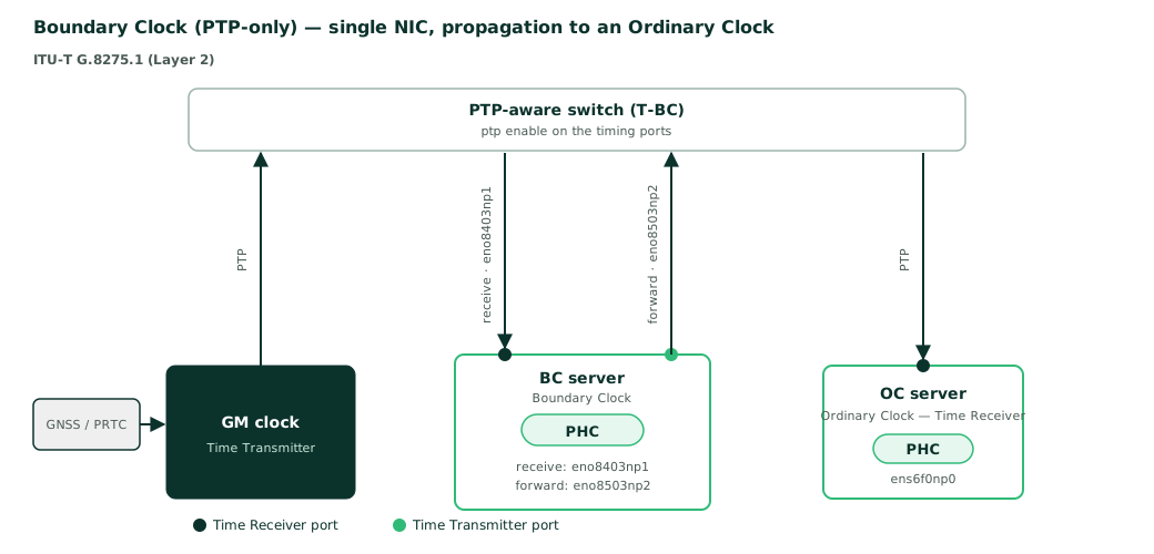
The scenario involves the following components:
Grandmaster (GM): the reference for the PTP domain (domain
24), normally locked to a GNSS/PRTC source (the test bench used here has no GNSS, hence the degradedgm.ClockClassshown later). It sends time on the upstream segment.PTP-aware switch: acts as a Boundary Clock (T-BC) on the timing path; every port carrying PTP has
ptp enable.Boundary Clock (BC server): a multi-port node on a single NIC that bridges two PTP segments. Its
eno8403np1port faces the upstream segment as a Time Receiver (SLAVE) and disciplines the NIC’s PHC;eno8503np2(andeno8603np3) face the downstream segment as Time Transmitters that regenerate PTP. The BC terminates the upstream timing chain and starts a new one downstream.Ordinary Clock (OC server): a single-port node (
ens6f0np0) on the downstream segment, where its only PTP master is the BC. It disciplines its local clocks from the time the BC regenerates.
The timing is handled by the linuxptp daemons on each node:
On the BC server, a single
ptp4linstance manages all its ports. The BMCA selects the GM as master oneno8403np1, which moves toSLAVEand disciplines the PHC.eno8503np2andeno8603np3are forced toserverOnly 1, so they act only as Time Transmitters. Because all ports share the same NIC PHC, the received time is directly available to the transmit ports; a Boundary Clock is implied automatically when more than one port is configured, so noclock_typeorts2phcsetting is needed.On the OC server,
ptp4lruns withclientOnly 1onens6f0np0, so the port only ever acts as a Time Receiver.phc2sysaligns the system clock to the PHC.On the OC server,
clientOnly 1is what guarantees it never becomes a master. ThelocalPriorityattribute — used by the G.8275.x BMCA only as a tie-breaker, when clockClass, clockAccuracy, variance and priority2 are equal, where a lower value is preferred — reinforces this ordering: the BC server keeps the default128, while the OC server uses the lower-preference250.
The BC bridges two separate PTP segments: an upstream segment between the GM and its
eno8403np1 port, and a downstream segment between its eno8503np2 port and the OC. These are kept
apart, for example on different VLANs of the switch or on separate networks. Because the
BC is the only master on the downstream segment, the OC synchronizes from the BC and
never directly from the GM.
As in Scenario 1a (Section 47.3, “Scenario 1a - Ordinary Clock (PTP-only)”), this scenario uses the non-forwardable multicast
MAC 01:80:C2:00:00:0E; standard bridges do not forward it, so every PTP-aware device
terminates and regenerates PTP. The same address must be set on every node of the
timing path.
Diagram
Configuration
Every switch port on the timing path (towards the GM, the BC and the OC) must have PTP enabled. The two cluster nodes are then configured as follows.
Boundary Clock (BC server)
Identify the PHC of the PTP NIC (
ethtool -T eno8403np1); on a single NIC all ports share the same PHC. In this example it is/dev/ptp1.Create
/etc/ptp4l-G.8275.1.conf. The receiving port[eno8403np1]has no role flag, so the BMCA selects it as Time Receiver;[eno8503np2]and[eno8603np3]are set toserverOnly 1to act as Time Transmitters. Declaring more than one port implies a Boundary Clock:Example 47.3: Boundary Clock configuration ## Telecom G.8275.1 — Boundary Clock (multi-port, single NIC) [global] domainNumber 24 priority2 255 dataset_comparison G.8275.x G.8275.portDS.localPriority 128 G.8275.defaultDS.localPriority 128 maxStepsRemoved 255 logAnnounceInterval -3 logSyncInterval -4 logMinDelayReqInterval -4 announceReceiptTimeout 3 ptp_dst_mac 01:80:C2:00:00:0E network_transport L2 summary_interval 3 message_tag "ptp4l" uds_address /var/run/ptp4l uds_ro_address /var/run/ptp4lro [eno8403np1] [eno8503np2] serverOnly 1 [eno8603np3] serverOnly 1
Point
ptp4lat this file in/etc/sysconfig/ptp4l:OPTIONS="-f /etc/ptp4l-G.8275.1.conf"
Optionally align the system clock with
phc2sysin/etc/sysconfig/phc2sys, using the shared NIC PHC as source:OPTIONS="-s /dev/ptp1 -w -m --uds_address /var/run/ptp4l --domainNumber 24"
Enable and start the services and verify that
eno8403np1is locked to the GM. The receiver port moves toSLAVEand the offset (rms) converges to a low value:# systemctl enable --now ptp4l phc2sys # journalctl -u ptp4l -f ptp4l[...]: "ptp4l" selected best master clock d0460c.ffff.05c130 ptp4l[...]: "ptp4l" port 1 (eno8403np1): UNCALIBRATED to SLAVE on MASTER_CLOCK_SELECTED ptp4l[...]: "ptp4l" rms 8 max 24 freq +10092 +/- 18 delay 211 +/- 2 ptp4l[...]: "ptp4l" rms 4 max 11 freq +10069 +/- 7 delay 210 +/- 2 ptp4l[...]: "ptp4l" rms 3 max 9 freq +10070 +/- 6 delay 213 +/- 3
Ordinary Clock (OC server)
Identify the PHC of the PTP interface (
ethtool -T ens6f0np0); in this example it is/dev/ptp1.Create
/etc/ptp4l-G.8275.1.confwith a single port andclientOnly 1, so the node only ever acts as a Time Receiver. The higherlocalPriority(250) keeps it below the BC in the BMCA:Example 47.4: Ordinary Clock configuration ## Telecom G.8275.1 — Ordinary Clock (Time Receiver) [global] domainNumber 24 priority2 255 dataset_comparison G.8275.x G.8275.portDS.localPriority 250 G.8275.defaultDS.localPriority 250 maxStepsRemoved 255 logAnnounceInterval -3 logSyncInterval -4 logMinDelayReqInterval -4 announceReceiptTimeout 3 clientOnly 1 ptp_dst_mac 01:80:C2:00:00:0E network_transport L2 summary_interval 3 message_tag "ptp4l" uds_address /var/run/ptp4l uds_ro_address /var/run/ptp4lro [ens6f0np0]
Configure
/etc/sysconfig/ptp4land/etc/sysconfig/phc2sysas for the BC (thephc2syssource is the PHC ofens6f0np0), then enable and start the services:# /etc/sysconfig/ptp4l OPTIONS="-f /etc/ptp4l-G.8275.1.conf" # /etc/sysconfig/phc2sys OPTIONS="-s /dev/ptp1 -w -m --uds_address /var/run/ptp4l --domainNumber 24"
Verify that
ens6f0np0is locked to the regenerated time from the BC. The port moves toSLAVEand the offset (rms) stabilizes:# journalctl -u ptp4l -f ptp4l[...]: "ptp4l" selected best master clock d0460c.ffff.05c130 ptp4l[...]: "ptp4l" port 1 (ens6f0np0): UNCALIBRATED to SLAVE on MASTER_CLOCK_SELECTED ptp4l[...]: "ptp4l" rms 15 max 34 freq +11699 +/- 25 delay 468 +/- 5 ptp4l[...]: "ptp4l" rms 13 max 30 freq +11701 +/- 23 delay 468 +/- 4 ptp4l[...]: "ptp4l" rms 14 max 30 freq +11697 +/- 24 delay 467 +/- 4The OC takes its time from the upstream Boundary Clock, which is its immediate master. The
selected best master clockline, however, reports the Grandmaster identity (d0460c.ffff.05c130, the GM) and not the Boundary Clock’s: a Boundary Clock forwards the Grandmaster identity unchanged while advertising its own port as the parent, so the chain stays traceable to the Grandmaster. To see both identities explicitly, query the parent data set on the OC (example output):# pmc -f /etc/ptp4l-G.8275.1.conf -u -b 0 'GET PARENT_DATA_SET' sending: GET PARENT_DATA_SET 507c6f.fffe.4ae178-0 seq 0 RESPONSE MANAGEMENT PARENT_DATA_SET parentPortIdentity 000000.fffe.001101-2 parentStats 0 observedParentOffsetScaledLogVariance 0xffff observedParentClockPhaseChangeRate 0x7fffffff grandmasterPriority1 128 gm.ClockClass 165 gm.ClockAccuracy 0xfe gm.OffsetScaledLogVariance 0xffff grandmasterPriority2 120 grandmasterIdentity d0460c.ffff.05c130The two identities differ, which is exactly what a Boundary Clock deployment should show:
parentPortIdentity(000000.fffe.001101-2) — the immediate master: the Boundary Clock’s transmit port, the clock the OC actually receives time from.grandmasterIdentity(d0460c.ffff.05c130) — the root of the timing tree: the Grandmaster, forwarded unchanged through the Boundary Clock.The
gm.ClockClass,gm.ClockAccuracyandgrandmasterPriorityvalues carry the Grandmaster’s advertised quality used by the BMCA. If the two identities were equal, the OC would be synchronizing directly from a Grandmaster, with no Boundary Clock in the path.
CAPI automation
To deploy this scenario using the automated provisioning workflow, use the generic Cluster API template described in Fully automated directed network provisioning (Section 55.1, “Precision Time Protocol (PTP)”) on each node, overriding its placeholders with the values below.
| Placeholder | Value |
|---|---|
|
|
| Copy the content from the Boundary Clock configuration above (Example 47.3, “Boundary Clock configuration”). |
|
|
|
|
| Placeholder | Value |
|---|---|
|
|
| Copy the content from the Ordinary Clock configuration above (Example 47.4, “Ordinary Clock configuration”). |
|
|
|
|
47.6 Scenario 2b - Boundary Clock (Hybrid mode: PTP & SyncE) with Multiport Single NIC including propagation to Ordinary Clock server #
This scenario is not yet supported; it will be included in a future SUSE Telco Cloud release.
47.7 Scenario 3a - Boundary Clock (PTP-only) Multi-NIC with internal timing module (DPLL GNR-D based) #
Explanation
SUSE Telco Cloud supports precise timing on a variety of platforms, including the latest Intel Granite Rapids-D based designs (GNR-D). These servers typically include an embedded high-speed Ethernet controller and one or more add-in cards (AICs) with an Ethernet controller for additional ports. Contrary to previous platform generations, they are also equipped with a dedicated DPLL that routes the timing signals across the system and the different NICs internally, no longer requiring external cabling to keep all NIC PHCs in sync. The overall deployment is thus simplified, but specific steps and software components are required, such as boot-time DPLL and internal signal configuration.
This scenario extends Scenario 2a (Section 47.5, “Scenario 2a - Boundary Clock (PTP-only) with Multiport Single NIC including propagation to Ordinary Clock server”) to a Boundary Clock (BC)
built on several NICs, entirely over ITU-T G.8275.1 (PTP-only, Layer 2). One port of the
integrated controller receives PTP from the Grandmaster and the add-in cards regenerate
PTP downstream. Unlike the single-NIC case, each NIC has its own PHC; the on-board DPLL
and ts2phc keep them aligned, and one ptp4l instance runs per PHC.
In this SUSE Telco Cloud release this scenario is only supported for the "default" (i.e., non "PREEMPT_RT") kernel flavour. Support for the "RT" kernel flavour will be added in a following release.
Download and install the latest kernel driver for the Intel 800 Series Network Devices from the Intel website.
Select the zip file containing the "ice_RPM_Files", unpack the archive and install the
ice-kmp-default-*sles16sp0.x86_64.rpm. This RPM contains, for example,ice-kmp-default-2.4.5_k6.12.0_160000.5-1.sles16sp0.x86_64.rpm:# transactional-update pkg install ice-kmp-default-2.4.5_k6.12.0_160000.5-1.sles16sp0.x86_64.rpmReboot the server to make the change persistent and effective.
A Dell PowerEdge XR8720t system is used as the reference system throughout the examples; the kernel interfaces and port configuration might be different on a different GNR-D server. Adjust the device names accordingly.
A telco deployment is assumed and the telco profile G.8275.1 is used throughout the following sections.
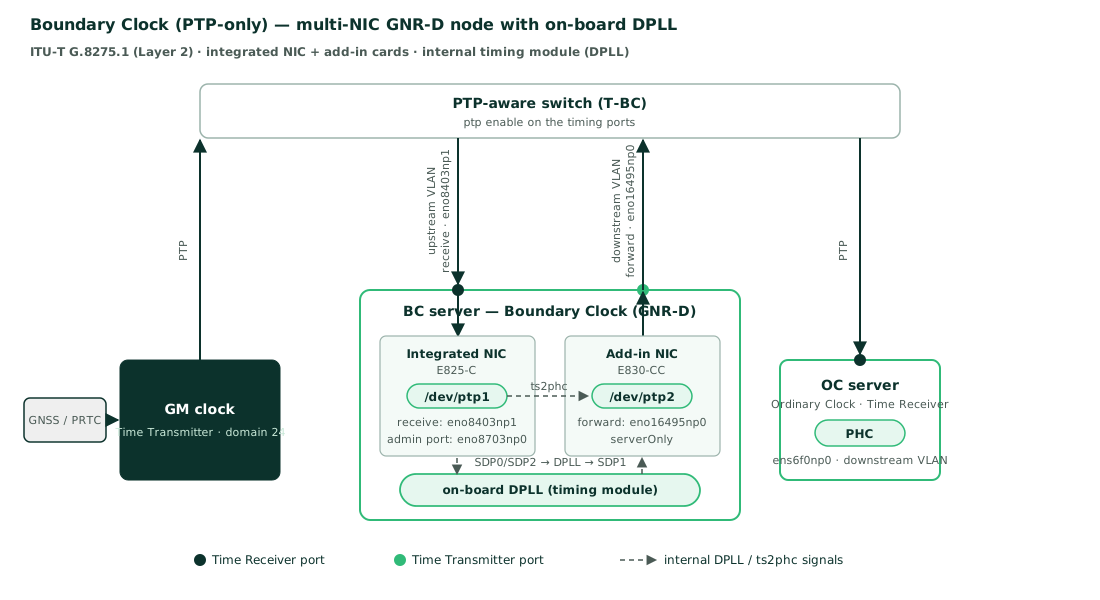
The scenario involves the following components:
Grandmaster (GM): the reference for the PTP domain (domain
24), on the upstream segment.PTP-aware switch: acts as a Boundary Clock (T-BC) on the timing path; every port carrying PTP has
ptp enable. The upstream and downstream segments are kept apart on different VLANs of the switch (a dedicated VLAN for each segment).Boundary Clock (BC server): the GNR-D node. Its integrated controller receives PTP from the GM on
eno8403np1and disciplines the integrated PHC (/dev/ptp1). The on-board DPLL distributes that timing to the add-in cards andts2phckeeps their PHCs (/dev/ptp2,/dev/ptp3) aligned with/dev/ptp1. Each add-in card regenerates PTP downstream (for example oneno16495np0), acting as a Time Transmitter.Ordinary Clock (OC server): a single-port node (
ens6f0np0) on the downstream segment, whose only PTP master is the BC.
The timing on the BC server is handled by several linuxptp daemons working together,
because the PHCs are physically separate:
A
ptp4linstance on the integrated controller (/dev/ptp1) runs the PTP protocol oneno8403np1. The BMCA selects the GM as master, the port moves toSLAVEandptp4ldisciplines/dev/ptp1.The on-board DPLL is wired so that the integrated PHC drives it through the SDP pins, and the DPLL in turn drives the add-in cards' clocks. This is the internal replacement for the external 1PPS cabling used on previous platforms.
ts2phckeeps the add-in cards' PHCs aligned to/dev/ptp1from the signal the DPLL distributes.A separate
ptp4linstance per add-in card (/dev/ptp2,/dev/ptp3) regenerates PTP on its ports, all forced toserverOnly 1(Time Transmitters).A Boundary Clock must forward the Grandmaster’s ancillary attributes (clock class, accuracy, and so on) in addition to time. This happens automatically only within a single
ptp4linstance, sopmcis used to forward those values from the integrated instance to the add-in instances (see step 5).pmc(PTP management client) is thelinuxptptool that queries and updates the runtime state of a runningptp4linstance over its management socket.
On the integrated controller only one of its ports is the administrative port that
manages the PHC. Inspect /sys/class/ptp/ptp1/device/net/ to find it (for example eno8703np0);
it is the port used to configure the DPLL signals, and it is not necessarily the port that
carries PTP (eno8403np1).
The setup described here is completely static. If the GM becomes unavailable, downstream synchronization relies exclusively on the host holdover capabilities; no automatic switching to a different time reference is performed.
Diagram
Configuration
Every switch port on the timing path must have PTP enabled. The BC server is then brought
up in the order below. Each runtime step is also mapped to a systemd unit so that the
configuration survives reboots and can be automated with Cluster API (see
the GNR-D CAPI automation (Section 55.1.2, “GNR-D multi-NIC scenarios (DPLL)”)). The OC server is configured exactly as in
Scenario 2a (Section 47.5, “Scenario 2a - Boundary Clock (PTP-only) with Multiport Single NIC including propagation to Ordinary Clock server”).
Identify the PTP devices and the integrated controller.
List the PTP clocks and the PCI device each is bound to:
# ls -l /sys/class/ptp/
lrwxrwxrwx 1 root root 0 ... ptp1 -> ../../devices/pci0000:12/0000:12:04.0/0000:13:00.0/ptp/ptp1
lrwxrwxrwx 1 root root 0 ... ptp2 -> ../../devices/pci0000:6b/0000:6b:02.0/0000:6c:00.0/ptp/ptp2
lrwxrwxrwx 1 root root 0 ... ptp3 -> ../../devices/pci0000:6b/0000:6b:06.0/0000:6e:00.0/ptp/ptp3
Run
lspcito identify each device type, allowing you to distinguish between the integrated controller and the add-in cards:# lspci -s 0000:13:00.0 13:00.0 Ethernet controller: Intel Corporation Ethernet Connection E825-C for SFP (rev 04) # lspci -s 0000:6c:00.0 6c:00.0 Ethernet controller: Intel Corporation Ethernet Controller E830-CC for SFP # lspci -s 0000:6e:00.0 6e:00.0 Ethernet controller: Intel Corporation Ethernet Controller E830-CC for SFPThis reference server has an Intel E825-C integrated controller (
/dev/ptp1) and two E830-CC add-in cards (/dev/ptp2,/dev/ptp3).Identify the administrative port of the integrated controller, which manages its PHC:
# ls /sys/class/ptp/ptp1/device/net/
eno8703np0
# ethtool -i eno8703np0
driver: ice
version: 2.4.5
[...]
Configure the internal timing signals (DPLL).
Wire the integrated PHC to the DPLL and let the DPLL feed the add-in cards, using the administrative port found above (
eno8703np0) and the correctptpNindices:Example 47.5:01-gnrd-startup-setup.sh##!/bin/bash # The admin port that manages the PHC is under /sys/class/ptp/ptp1/device/net/ (e.g. eno8703np0). # Only one port of the integrated E825-C NIC exposes it. # Let the DPLL drive the Ethernet clock on the integrated controller echo 4 1 > /sys/class/net/eno8703np0/device/tspll_cfg # Feed the DPLL from the integrated PHC through the SDP pins: # SDP0 -> 1 pulse per second (1PPS, 1 Hz): enable the pin, then set a 1 s period echo 2 2 > /sys/class/ptp/ptp1/pins/SDP0 echo 2 0 0 1 0 > /sys/class/ptp/ptp1/period # SDP2 -> 1000 pulses per second (1kPPS, 1 kHz): enable the pin, then set a 1 ms period echo 2 1 > /sys/class/ptp/ptp1/pins/SDP2 echo 1 0 0 0 1000000 > /sys/class/ptp/ptp1/period # Propagate the pulses from the DPLL to the add-in cards (SDP1 on each add-in PHC) echo 1 1 > /sys/class/ptp/ptp2/pins/SDP1 echo 1 1 > /sys/class/ptp/ptp3/pins/SDP1These settings are lost on reboot, so run the script at boot from a oneshot
systemdunit, ordered beforets2phcandptp4l:# /etc/systemd/system/gnrd-ptp-dpll-setup.service [Unit] Description=GNR-D PTP DPLL and internal signal setup Before=ts2phc.service ptp4l@nac.service ptp4l@aic1.service ptp4l@aic2.service [Service] Type=oneshot RemainAfterExit=yes ExecStart=/usr/local/bin/01-gnrd-startup-setup.sh [Install] WantedBy=multi-user.targetAlign the add-in cards' PHCs with
ts2phc.ts2phc("time stamp to PHC") aligns the add-in cards' PHCs to a reference clock. Here, the reference is the PHC from the integrated NIC (/dev/ptp1, already disciplined by the GM through itsptp4linstance), passed on the command line with-s /dev/ptp1. The on-board DPLL delivers the 1PPS derived from that reference to each add-in card on itsSDP1pin;ts2phctimestamps those input pulses (EXTTS) and steps each add-in PHC accordingly, so every PHC in the node ends up sharing the same time.NoteAligning the add-in PHCs takes two complementary settings, at different levels:
Hardware: the
SDP1input pin of each add-in PHC must be enabled for the on-board DPLL to deliver the 1PPS pulse to it. This is done in the DPLL setup script of the previous step (echo 1 1 > /sys/class/ptp/ptpN/pins/SDP1).Software:
ts2phcmust be told to timestamp that input and step the PHC. This is what the configuration below does (ts2phc.channel,ts2phc.pin_index,ts2phc.extts_polarity).
Without enabling the pin, the pulse never reaches the PHC; without the
ts2phcconfiguration the pulse is never applied to it. Both are required.Create its configuration file:
Example 47.6:/etc/ts2phc-cf-all.cfg—ts2phcconfiguration file #[global] use_syslog 0 verbose 1 logging_level 7 ts2phc.pulsewidth 100000000 [eno16495np0] ts2phc.channel 1 ts2phc.extts_polarity rising ts2phc.pin_index 1 [eno16595np0] ts2phc.channel 1 ts2phc.extts_polarity rising ts2phc.pin_index 1
Each add-in card is configured through a section named after its first port (
[eno16495np0],[eno16595np0]), which identifies the PHC to discipline. The parameters map the DPLL pulse to that card:ts2phc.pin_indexandts2phc.channel: the pin and channel where the DPLL delivers the 1PPS (SDP1in this setup, hencepin_index 1).ts2phc.extts_polarity: the pulse edge to timestamp (rising).ts2phc.pulsewidth: the expected input pulse width, in nanoseconds (100 ms here).Run it manually as
ts2phc -f /etc/ts2phc-cf-all.cfg -s /dev/ptp1 -m, or letsystemdmanage it through/etc/sysconfig/ts2phc:# /etc/sysconfig/ts2phc OPTIONS="-f /etc/ts2phc-cf-all.cfg -s /dev/ptp1 -m"
Run one
ptp4linstance per PHC.The integrated controller runs a BMCA-driven instance (the receiver), and each add-in card runs an instance with all ports forced to
serverOnly 1. Each instance must use a different control and read-only socket. Create the three configuration files:Example 47.7:/etc/ptp4l-nac.conf— integrated controller (/dev/ptp1) ## Telecom G.8275.1 — integrated controller (receiver) [global] domainNumber 24 priority2 255 dataset_comparison G.8275.x G.8275.portDS.localPriority 128 G.8275.defaultDS.localPriority 128 maxStepsRemoved 255 logAnnounceInterval -3 logSyncInterval -4 logMinDelayReqInterval -4 announceReceiptTimeout 3 ptp_dst_mac 01:80:C2:00:00:0E network_transport L2 summary_interval 3 message_tag "ptp4l-nac" uds_address /var/run/ptp4l-nac uds_ro_address /var/run/ptp4lro-nac [eno8403np1]
The integrated instance declares only
eno8403np1, the port that receives PTP from the GM, and sets noserverOnlyorclientOnlyon it: it relies on the BMCA to assign the role. With a GM reachable oneno8403np1, the BMCA selects it as the Time Receiver (SLAVE) and disciplines/dev/ptp1. The other ports of the integrated controller are not declared, because on this node the downstream regeneration is performed by the add-in cards rather than by the integrated controller. The add-in cards, in contrast, forceserverOnly 1because they must always be Time Transmitters — they take their time from the DPLL andts2phc, not by receiving PTP, so they must never be elected as receivers. If tighter control is needed, add theserverOnlyorclientOnlyflag explicitly under the interface.The
G.8275.portDS.localPriorityandG.8275.defaultDS.localPriorityvalues (128on the integrated instance,250on the add-in cards) act as a G.8275.x BMCA tie-breaker: they are compared only afterclockClass,clockAccuracy, variance andpriority2, and a lower value is preferred. Keeping the default128on the integrated instance makes it outrank the add-in instances (250), which keeps the Time Transmitter/Time Receiver ordering within the node deterministic and drives which port the BMCA elects, as reflected in the port states reported byptp4l.Example 47.8:/etc/ptp4l-aic1.conf— add-in card 1 (/dev/ptp2) ## Telecom G.8275.1 — add-in card (Time Transmitter) [global] domainNumber 24 priority2 255 dataset_comparison G.8275.x G.8275.portDS.localPriority 250 G.8275.defaultDS.localPriority 250 maxStepsRemoved 255 logAnnounceInterval -3 logSyncInterval -4 logMinDelayReqInterval -4 announceReceiptTimeout 3 ptp_dst_mac 01:80:C2:00:00:0E network_transport L2 summary_interval 3 message_tag "ptp4l-aic1" uds_address /var/run/ptp4l-aic1 uds_ro_address /var/run/ptp4lro-aic1 [eno16495np0] serverOnly 1
Example 47.9:/etc/ptp4l-aic2.conf— add-in card 2 (/dev/ptp3) ## Telecom G.8275.1 — add-in card (Time Transmitter) [global] domainNumber 24 priority2 255 dataset_comparison G.8275.x G.8275.portDS.localPriority 250 G.8275.defaultDS.localPriority 250 maxStepsRemoved 255 logAnnounceInterval -3 logSyncInterval -4 logMinDelayReqInterval -4 announceReceiptTimeout 3 ptp_dst_mac 01:80:C2:00:00:0E network_transport L2 summary_interval 3 message_tag "ptp4l-aic2" uds_address /var/run/ptp4l-aic2 uds_ro_address /var/run/ptp4lro-aic2 [eno16595np0] serverOnly 1
NoteAs in Scenario 2a (Section 47.5, “Scenario 2a - Boundary Clock (PTP-only) with Multiport Single NIC including propagation to Ordinary Clock server”), every node on the timing path uses the same non-forwardable G.8275.1 multicast MAC
01:80:C2:00:00:0E, including the downstream OC.Manage the instances with a templated
systemdunit that reads/etc/ptp4l-<instance>.conf:# /etc/systemd/system/ptp4l@.service [Unit] Description=PTP Boundary Clock instance %i After=gnrd-ptp-dpll-setup.service Requires=gnrd-ptp-dpll-setup.service [Service] ExecStart=/usr/sbin/ptp4l -f /etc/ptp4l-%i.conf [Install] WantedBy=multi-user.targetEnable and start the three instances:
# systemctl enable --now ptp4l@nac ptp4l@aic1 ptp4l@aic2Forward the Grandmaster parameters across the
ptp4linstances.A Boundary Clock must forward not only time but also the Grandmaster’s ancillary parameters (clock class, accuracy, UTC offset, and so on). This happens automatically between ports of the same
ptp4linstance, but not across the separate instances that manage different PHCs. The values are applied at runtime withpmcover each instance’s UDS socket (SET GRANDMASTER_SETTINGS_NP).ImportantThe values applied with
pmcare held only in the runningptp4lprocess; they are not written to the.conffile and do not survive a restart. If aptp4linstance is restarted, it reverts to the file defaults and the values must be forwarded again. Automate the forwarding (see below) rather than running it once by hand.Once the integrated controller is locked to the GM, query the Grandmaster values. The helper below takes the configuration file of the instance to query as its argument:
Example 47.10:get_pmc_values.sh— query the Grandmaster values from aptp4linstance ##!/bin/bash # Retrieve Grandmaster information via pmc for the given ptp4l config file set -euo pipefail echo "PARENT_DATA_SET (Grandmaster clock values):" pmc -f "$1" -u -b 0 'GET PARENT_DATA_SET' | grep gm echo "TIME_PROPERTIES_DATA_SET:" pmc -f "$1" -u -b 0 'GET TIME_PROPERTIES_DATA_SET'Then forward those values to the add-in instances. The following script reads the values from the integrated instance and applies them to each add-in instance. Edit the "Input variables" section to match your configuration file names, and run it once the system is synchronized to a GM:
Example 47.11:04-ptp-forward-GM.sh— forward the Grandmaster values to the add-in instances ##!/bin/bash set -euo pipefail ################## Input variables ################## VERBOSE=1 CONFIG_FILE_NAC=/etc/ptp4l-nac.conf CONFIG_FILES_AICS=(/etc/ptp4l-aic1.conf /etc/ptp4l-aic2.conf) ##################################################### # Check the system is synchronized to a GM GM_PRESENT=$(pmc -f ${CONFIG_FILE_NAC} -u -b 0 'GET TIME_STATUS_NP' | awk '/gmPresent/ {print $2}') if [ -z "$GM_PRESENT" ]; then echo "Failed to get GM value from ptp4l instance for NAC, exiting..." exit 1 elif [ "${GM_PRESENT}" != "true" ]; then echo "No GM present, exiting..." exit 1 fi # Get the "upstream" Grandmaster values PDS_GM_VALUES=$(pmc -f ${CONFIG_FILE_NAC} -u -b 0 'GET PARENT_DATA_SET' | awk 'BEGIN {ORS=" "} /gm./ {print $2}') TPDS_GM_VALUES=$(pmc -f ${CONFIG_FILE_NAC} -u -b 0 'GET TIME_PROPERTIES_DATA_SET' | awk 'BEGIN {ORS=" "} NR>2 {print $2}') if [ -z "$PDS_GM_VALUES" ]; then echo "No PARENT_DATA_SET values retrieved, exiting ..." exit 2 elif [ -z "$TPDS_GM_VALUES" ]; then echo "No TIME_PROPERTIES_DATA_SET values retrieved, exiting ..." exit 2 fi # Unpack from PARENT_DATA_SET read CLOCK_CLASS CLOCK_ACCURACY VARIANCE <<< $PDS_GM_VALUES # Unpack from TIME_PROPERTIES_DATA_SET read UTC_OFFSET LEAP_61 LEAP_59 UTC_OFFSET_VALID PTP_TIMESCALE T_TRACEABLE F_TRACEABLE T_SOURCE <<< $TPDS_GM_VALUES if [ "$VERBOSE" -eq 1 ]; then echo "Read from PARENT_DATA_SET: clockClass=${CLOCK_CLASS} clockAccuracy=${CLOCK_ACCURACY} offsetScaledLogVariance=${VARIANCE}" echo "Read from TIME_PROPERTIES_DATA_SET: currentUtcOffset=${UTC_OFFSET} leap61=${LEAP_61} leap59=${LEAP_59}" \ "currentUtcOffsetValid=${UTC_OFFSET_VALID} ptpTimescale=${PTP_TIMESCALE} timeTraceable=${T_TRACEABLE}" \ "frequencyTraceable=${F_TRACEABLE} timeSource=${T_SOURCE}" fi # Forward these values to the "downstream" Time Receivers, updating the ptp4l instances for FILE in "${CONFIG_FILES_AICS[@]}"; do if [ "$VERBOSE" -eq 1 ]; then echo "Updating GRANDMASTER_SETTINGS_NP (${FILE})" fi pmc -f ${FILE} -u -b 0 'SET GRANDMASTER_SETTINGS_NP clockClass '${CLOCK_CLASS}' clockAccuracy '${CLOCK_ACCURACY}' offsetScaledLogVariance '${VARIANCE}' currentUtcOffset '${UTC_OFFSET}' leap61 '${LEAP_61}' leap59 '${LEAP_59}' currentUtcOffsetValid '${UTC_OFFSET_VALID}' ptpTimescale '${PTP_TIMESCALE}' timeTraceable '${T_TRACEABLE}' frequencyTraceable '${F_TRACEABLE}' timeSource '${T_SOURCE}'' &> /dev/null if [ $? -ne 0 ]; then echo "Failed to update ptp4l instance using config file \"${FILE}\", exiting ..." exit 1 fi doneBecause the values are not persistent, run this script from a
systemdtimer so that they are refreshed periodically and after any instance restart:# /etc/systemd/system/ptp-forward-gm.service [Unit] Description=Forward Grandmaster parameters to the add-in ptp4l instances Wants=ptp4l@nac.service ptp4l@aic1.service ptp4l@aic2.service After=ptp4l@nac.service ptp4l@aic1.service ptp4l@aic2.service [Service] Type=oneshot SELinuxContext=system_u:system_r:unconfined_t:s0 ExecStart=/usr/local/bin/04-ptp-forward-GM.sh# /etc/systemd/system/ptp-forward-gm.timer [Unit] Description=Refresh forwarded Grandmaster parameters [Timer] OnBootSec=2min OnUnitActiveSec=5min [Install] WantedBy=timers.targetThe effect is visible by querying an add-in
ptp4linstance on the BC: before forwarding, the node advertises its file defaults; after forwarding begins, it advertises the Grand Master’s actual values (which then propagate to the downstream OC). For example,gm.ClockClasschanges:# ./get_pmc_values.sh /etc/ptp4l-aic1.conf # before forwarding gm.ClockClass 165 gm.ClockAccuracy 0xfe gm.OffsetScaledLogVariance 0xffff # ./get_pmc_values.sh /etc/ptp4l-aic1.conf # after forwarding gm.ClockClass 8 gm.ClockAccuracy 0xfe gm.OffsetScaledLogVariance 0xffffOptionally, derive the system clock from PTP with
phc2sys, using the integrated PHC as source (/etc/sysconfig/phc2sys):OPTIONS="-f /etc/ptp4l-nac.conf -s /dev/ptp1 -c CLOCK_REALTIME -w"
CAPI automation
To deploy this scenario with the automated provisioning workflow, use the GNR-D-specific
Cluster API template described in Fully automated directed network
provisioning — GNR-D scenarios (Section 55.1.2, “GNR-D multi-NIC scenarios (DPLL)”). Unlike the standard scenarios, it deploys several ptp4l
instances, the ts2phc service, the DPLL boot-time setup and the Grandmaster forwarding
timer, so it requires the additional configuration files and systemd units listed above.
Override its placeholders with the values below.
| Placeholder | Value |
|---|---|
| Copy the content from 01-gnrd-startup-setup.sh (Example 47.5, “ |
| Copy the content from 04-ptp-forward-GM.sh (Example 47.11, “ |
| Copy the content from /etc/ts2phc-cf-all.cfg (Example 47.6, “ |
|
|
| Copy the content from /etc/ptp4l-nac.conf (Example 47.7, “ |
| Copy the content from /etc/ptp4l-aic1.conf (Example 47.8, “ |
| Copy the content from /etc/ptp4l-aic2.conf (Example 47.9, “ |
47.8 Scenario 3b - Boundary Clock (Hybrid mode: PTP & SyncE) Multi-NIC with internal timing module (DPLL GNR-D based) #
This scenario is not yet supported; it will be included in a future SUSE Telco Cloud release.